
Wednesday, June 15, 2011
Final A1 Board
Renders
 |
| Diagram showing movement. |
 |
| Timber screen roof casting shadows on the floor |
 |
| North Elevation |
 |
| Floor Plan - the pattern on the central floor is the same as the shadows cast by the timber screen |
Site Photos
 |
| Picture of city cat...will need to for montages |
 |
| Close up of site...about as close as one can get. |
 |
| Site in context |
 |
| Front view of site....could use this as a background to a section to put it in context. |
 |
| Heritage building and damaged bank |
 |
| View to from site |
Building in ArchiCAD
 |
| Building the multi level floor |
 |
| Building the roof, keeping the concept of multiple roofs that overlap to provide shelter. I use metal sheeting (currently on heritage buildings) and timber battens as I detail earlier. |


 |
| Strong use of curves to allow for smooth flow of people. The curves are also an abstraction of the wave form. |
Refining the Ideas
 |
| Working in section - Trying a multi level space |
 |
| Rough floor plan of a multi level space |
 |
| Experimentation with the form of a wave for the stairs |
Review with Tutor (Ruwan)
 |
| Sketch/conversation with tutor |
Converting Ideas into 3d


Columns

Roof and Columns


The detail shows how I planed to use timber battens and glass to allow light but to block all the other elements. This detail i used in my final design.
Sketch Design

Starting Project 3
I struggled to continue on to project 3 as I did not really like my design for project 2. My thoughts kept moving towards a new design rather than building on the old one.
So I decided to change the form...but keep the concepts and features of the old design. I kept the bike facility, the timber battens, the multiple roofs, the curved beam and many other things. But I let myself change the form using these "features" as constraints.
I also reduced the size of the ferry terminal. In project 2 I think I had too huge a space for a ferry terminal. This allowed me to focus on a few details.
Wednesday, May 4, 2011
Bike Racks

At first I placed standard bike racks from archiCAD. This looked very standard and obviously place from a generic library. So I sketched out some ideas for a bike rack based on the Brisbane river and the organic nature of my structure. I narrowed it down to 3 options and finally chose option 3.
I sketched option 3 to lock 2 bikes, but then thought bikers often like to chain their wheels and frame too. So I have allowed 1 bike per bike stand.
The render below shows the bike racks in context.
Slice Through Animation
I tried a slice through my model to explain how different roofs and levels have been created. The quality is not very good so I will have to render at a higher resolution.
Tuesday, May 3, 2011
Sketch Section

This is a section of my terminal. Although this is not what it looks like now, i drew this as a starting point to put some of my ideas on paper. The connection shooting out the top is to link it to the other developments in the tutorial. I did not develop this idea as i was not too sure if it was necessary and weather it would fit with other's proposals.
The section does explain my design with 2 roofs. one large external roof, over an internal structure that can be locked or used for commercial / facilities for the terminal.
Defining Space

The large bike facility is to allow a bike company to set up a shop at the terminal that can also service/fix bikes while bikers are at work. Showers and lockers have also been provided making it easier for more people to ride bikes. Large number of bike parking spaces have been provided outside the bike shop. With some negotiation, members of the bike shop could possible ride the ferry for free as they will probably only be traveling one or two stops to the CBD.
Tuesday, April 19, 2011
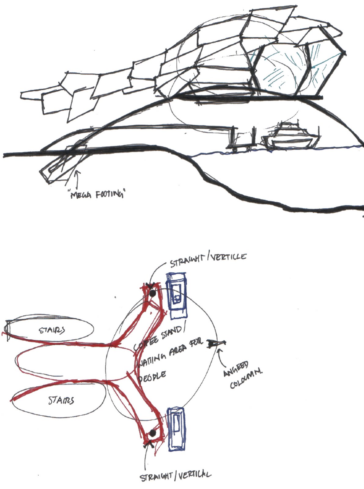
Idea Generation

I then identified places that I need to detail further, for eg, where beams and land meet pose good opportunities to treat the connection as a sculpture. After drawing a few ideas, I tried to model the connection on 3ds MAX but was unable to create something appealing or close to my sketch. Further work/practice is need in this area.
The image above shows this progression.
Space Planning

Wednesday, April 13, 2011


Tuesday, April 5, 2011
Ninja equation
 How I translate Calatrava's proposal for the new transport hub on the world trade centre site into a ninja equation.
Initial sketches of Folie


Wednesday, March 23, 2011
Experimenting with seating


Having a physical model allowed me to freely experiment with different seat positions. I intend to have the seats free of the structure for people to move around, depending on the activity taking place at the folie.
Experimenting with physical model
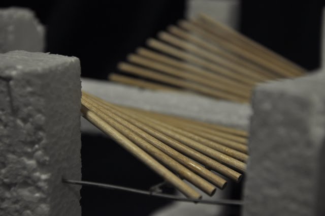


I made a physical model to experiment with how the solid mass of the structure will be supported by thin steel wire. This also gave me a chance to see how the timber battens look curving with the structure to reflect the Story Bridge. I think it worked well :-)
Sunday, March 20, 2011
Access Study
 Access study highlighted that the site was mainly a thoroughfare. Most major connections go straight past or around the site. To give people a reason to visit the site, I'm providing a structure that will frame a stage for performances. located between 4 major regions in Brisbane, public transport to areas around the site is not a problem, however direct transport to the site is not readily available. Majority of access will have to be by foot, bike or via proposed ferry stop.
Thursday, March 17, 2011
Change in direction
Since my last post i have decided to change my approach.
The Story Bridge has distinguished shape that has been constructed out of hard materials (steel and concrete). I'm using this concept as a starting point to my folie design. A mixture of concrete and timber will reflect a shape that relates to the story bridge, while integrating with the site.
The folie is to act as a stage the provides a shelter for performers (either musicians or actors/street performances) to run shows. It should protect from rain, so performers don't have to worry about their equipment. While it's not a stage it should be a spot to rest while on a walk/ride.
Wednesday, March 16, 2011
Inspiration

For the folie design, I'm taking inspiration from the kurilpa bridge and the story bridge. My reason for choosing the Kurilpa bridge is for it's tensegrity proprieties that i find fascinating. Tensegrity structures also allow for a very transparent construction. I hope that my folie will relate to the story bridge but also blend into the surroundings through it's transparent nature.
Tuesday, March 15, 2011

Subscribe to:
Posts (Atom)